Incremental Optical Encoders
A common question in robotics is: where am I? It's not hard to spin a robot's
wheels around, but often we want to move a specific distance, or turn clockwise
by a specific angle. Encoders provide a way of measuring the motor's position
so that you can do more consistent motion control. There are probably whole
books about different kinds of encoders, but this web page will just talk about
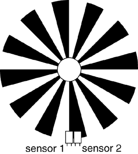
creating incremental encoders that look like this:
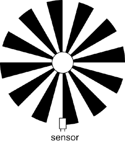
So, these shapes are pretty but what do you do with them? Imagine that this
pattern is fixed to a shaft so that it spins at the same rate as a motor
shaft or the wheel, and you put an optical sensor at one spot along the edge
of the wheel. The sensor tells at any time whether it sees black or white.
Then, if there are 24 divisions in the wheel, you can look at the pattern of
black/white reading to see how fast the wheel is turning around. Because 360
degrees divided by 24 divisions is 15 degrees/division, you can sense whenever
the shaft turns 15 degrees. But note that with one sensor you can't tell if
the wheel is moving clockwise or counterclockwise. For this, we would need
another sensor.
Optical Encoder with 1 Sensor
If you always know which direction the shaft is moving, then one sensor is
enough. But if you are changing direction frequently, or the load is changing,
you may want to measure the direction as well. If you are controlling an arm
and trying to lift an object, it could be so heavy that the arm is moving
downward even though the motor is pushing upward. Or if the robot is trying to
roll up an incline, you would want to know if you are progressing up the hill
or rolling down it. If you add another optical sensor, carefully placed in
relation to the first, you can detect the direction of motion in addition to
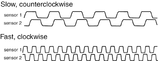
the speed. In the diagram below, you see that the distance between the two
sensors is half of one division. Whenever one sensor is on the boundary
between light and dark, the other is in the middle of a solid light or dark
area. This is the key!
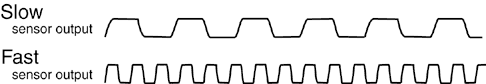
If the wheel is moving counterclockwise, sensor 1 sees a light or dark area
before it reaches sensor 2. If the wheel direction is reversed, then sensor 2
sees the light or dark first. (In the waveforms, high represents light and low
represents dark. Depending on your circuit it might be the opposite.) These
sensor readings are 90 degrees out of phase. A simple program in a
microcontroller can detect these transitions and turn it into a count that
increases when the wheel goes one direction and decreases when the wheel goes
the other direction. With two sensors there are two bits of digital
information, so you will need two input pins per optical encoder.
Optical Encoder with 2 Sensors
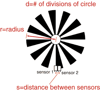
Here is a method for making an encoder with two sensors for your application.
If you only need speed sensing, you may want to skip down to the construction
section. The important variables are the radius of the circle (r), the
distance between the two optical sensors (s), and the number of divisions in
the wheel (d). The goal is to make it so that when one sensor sees a
transition, the other sensor is halfway through a light or dark region. Then
the waveforms are 90 degrees out of phase, and you can detect which way the
wheel is turning. The variables r, s, and d are drawn on this diagram.
Encoder Math
Here comes the algebra... The circumference of the circle is 2*PI*r, so when
it's divided into d divisions, the width of each division (along the circle)
is 2*PI*r/d. I'm taking a shortcut and assuming that each division is small
enough that the circle is basically flat for the width of the division.
Mathematically, I'm using the approximation sin(theta)=theta for small theta.
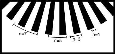
Now, we have seen that a distance between sensors (s) of one half division
gives the two waveforms 90 degrees out of phase. Also, you can use 1.5
divisions, 2.5 divisions, 3.5 divisions, etc. So the distance between sensors
can be 2*PI*r/d times (n/2) where n is an odd integer. Solve for d and you get
d=(n*PI*r)/s. The next diagram shows the graphical meaning of different values
of n. The marked distances represent the distance between sensors for values
of n=1, n=3, n=5, etc.
Graphical Interpretation of n
Why did I solve for d? I believe it is easiest to build the motor shaft and
attach the sensors first and measure r and s. The sensors should be about as
close as they can be. Then, choose a value of n, compute d and round to the
nearest even number, and make an encoder wheel with d divisions. Other
variations are possible of course, but it's much easier to measure accurately
than to build accurately. And it's easy, cheap, and quick to make optical
encoders for any value of n and d. A few considerations when choosing n and d:
- n must be odd
- d must be even. When you compute d, it will probably be some wierd
fraction so just round to the nearest even. If you're wondering why d must be
even, try to divide a circle into 5 divisions and color them alternating black
and white.
- If d is too large, you can exceed the resolution of your printer or
optical sensors. On a 600dpi laser printer, with a radius of 1 inch you might
get up to about d=600 divisions before the quality deteriorates. You could
use more divisions if you increase the radius of the encoder wheel. Or you
would probably get better resolution on a better quality printer. The specs
on optical sensors will often mention the smallest size of object they can
resolve, and with large values of d this will start to matter as well.
- With more encoder divisions, your processor will need to sample the encoder
inputs more frequently to avoid missing any transitions. If you are running
short on processor cycles, this could be important.
- Even when you compute the ideal values for the encoder and create it, you
may find that the waveforms are not really 90 degrees out of phase. The radius
measurement is tricky because it should be measured from the center of the axis
of rotation to the point where the optical sensor is most sensitive, but you
may not know where that is until you try it. Also, my assumption that sin(x)=x
is only perfect if d is very large, so it could contribute to error. The
best solution may be to print a few encoders close to the computed d, and see
which ones work best.
- It's not critical that the waveforms are precisely 90 degrees separated.
But if they are close to 0 degrees separated (in sync) or 180 degrees
separated, the transitions in the two sensors will be so close that you lose
all the benefits of having two sensors.
Building your own encoder
If you look for optical encoders in a catalog, you will probably find that
they are quite expensive! (Alternative: If you take apart a computer mouse,
you often find two tiny encoder wheels, one for X and Y motion. If you have
some of these lying around, you may not need to construct your own wheel.) I
soon decided to buy the optical sensors and make the encoder wheels myself.
You will need to choose between reflective and transmissive sensors.
Reflective means that the sensor emits light, which reflects off an object
then returns to the detector (which is close to the emitter). Transmissive
sensors produce light, which passes through a channel and is detected (or not)
on the opposite side. An object must block the light passing through the
channel to be noticed.
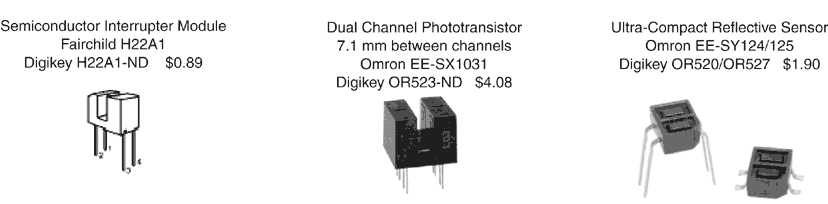
Here are a few types of optical sensors available. I have used the Omron
EE-SX1031 in a wheel encoder for a mobile robot. It's convenient because it
has two sensors in one package, and the datasheet tells you exactly how far
they are apart. Jones and Flynn suggest a Hamamatsu P5587 as a reflective
sensor, but I don't have a picture of it.
With a reflective sensor, the encoder wheel can be printed onto a sheet of
paper and mounted on some opaque surface. Jones and Flynn suggest that
the opaque surface should include several pieces of blank white paper to
reduce the amount of light that passes right through the white segments of
the encoder. It should probably also be attached to something rigid; you
don't want the paper flapping around.
When using a transmissive sensor, the encoder wheel needs to pass through the
channel to block the beam. An encoder pattern can be printed onto a
transparency and mounted on a clear surface. For best results, print onto a
transparency with a laser printer, or photocopy onto a transparency. (Ink from
an inkjet printer will smear if anything touches it. If you insist on using an
inkjet, then carefully place a wide strip of packaging tape over the whole
wheel to reduce smearing.) Then I suggest mounting it on a clear, thin disc
to keep it rigid. I make clear discs using a scroll saw:
- Draw the right size circle on paper using a compass.
- Take apart a CD case and tape the paper to it.
- Cut through both the paper and plastic with scroll saw, using the circle on
paper as a guide. Use a slow speed to avoid cracks. Wear eye protection!
- File the edges to smooth any sharp spots.
Then I attach the transparency to the clear disc using a square of Scotch
Removable Double-Coated Tape (or whatever works). Since the sensors only
need to look at the edge of the wheel, you can put whatever you want in the
middle of the wheel. Tape, glue, screws, etc. Drill a hole in the center of
the disc so that it fits onto the shaft.
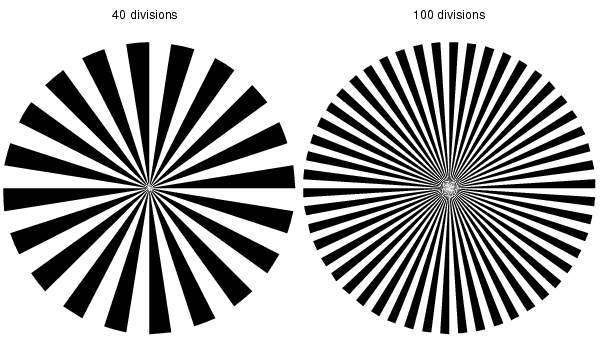
The first encoders I made were drawn with Adobe Illustrator. After making
10 or 20 different kinds, I got tired of the process and wrote a perl script to
quickly generate encoder wheels with a variable number of divisions. When you
run the script you get one page of Postscript output with up to four encoder
wheels on it. Here's a sample output, converted to a GIF so that you can see
it in your web browser.
In Unix, to get this output you would type:
  ./make-encoder.perl 40 100 > encoders.ps
  lpr encoders.ps
Download make-encoder.perl
Download sample output in Postscript
For Windows users: Perl is available for Windows too. Look for ActiveState perl or download Cygwin (a whole UNIX-like
environment, large download). If you don't have any software or a printer that
can handle postscript, check out www.ps2pdf.com which can convert postscript to
a PDF file, which almost everybody can read. Email me if you have trouble.
Please let me know if you have any suggestions for these pages. I'm not a
robotics expert, but I want to share what I have learned.